Hold the mission constant
Reference cruise speed 46.3 m/s and a nominal 12.25 m² wing area; retain the existing fuselage and V-tail concept.
The Robin ATL already existed. The question was whether a redesigned, naturally laminar-flow wing could make its electric-aircraft concept more aerodynamically efficient—without ignoring packaging and pitching-moment constraints.
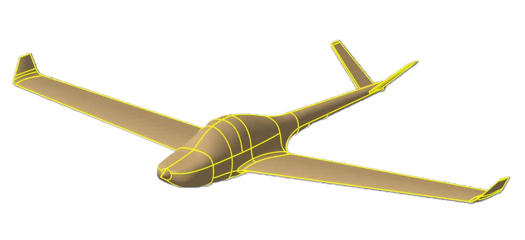 AIRCRAFT CAD · SUPPLIED SOURCE VIEW
ENGINEERING SUMMARY
The electric propulsion concept created a multi-objective design problem. The winning configuration needed competitive cruise efficiency, useful internal volume and manageable aerodynamic moments.
Reference cruise speed 46.3 m/s and a nominal 12.25 m² wing area; retain the existing fuselage and V-tail concept.
Assess wing span and taper, three airfoil candidates, and two winglet configurations—rather than optimizing one metric in isolation.
Compare the final and original wing at their cruise operating points, then distinguish later CFD visuals from the 2015 result.
With electric propulsion driving the design, the study retained the existing aircraft configuration while reassessing the wing. The natural-laminar-flow section, increased span and selected winglet are the principal aerodynamic changes.
Use the overlay to inspect the relative planform; this is an engineering schematic, not a reconstructed production drawing.
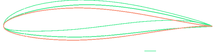
NACA 64A415 delivered a marginally higher predicted cruise L/D, but NACA 63-215 was selected for its more favorable pitching moment at comparable aerodynamic efficiency.
The decision is backed by the study's operating-point results, not just attractive CAD. Read the numbers alongside the model boundary.
The model compares wing-only aerodynamic coefficients at the evaluated cruise operating points. Same nominal wing area: 12.25 m².
Result from the 2015 XFLR5 wing-design study. This is not a measured aircraft-level drag reduction or a flight-test result.
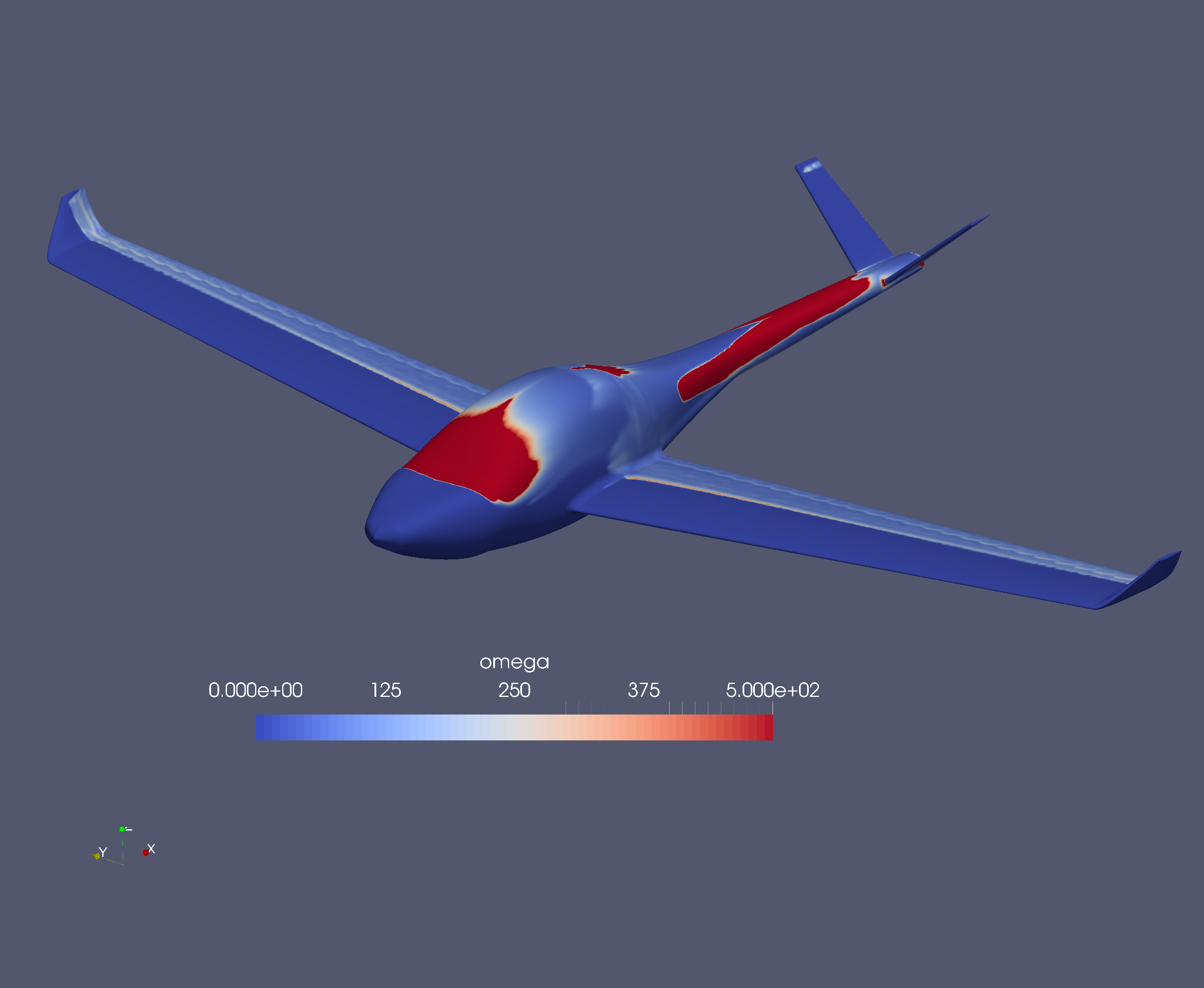
Original, unmodified CFD renders from separately supplied materials. Explore fields and mesh detail without confusing the ω quantity with a verified transition map.
Recorded shape-optimization frames and an approximate coefficient history illustrate further numerical work. The modest drag reduction shown here is distinct from the original 31% wing L/D design comparison.
Approximate values digitized from the supplied screenshot, not recovered from a solver CSV. Minimum occurs around iteration 10; small rebound follows.
2015 master's thesis, University of Zagreb: conceptual redesign of the Robin ATL wing for the eFly electric-propulsion conversion. The study retains the existing fuselage and V-tail concept and focuses on the wing. These are historical design-study predictions, not an implemented or certificated design.
Initial XFOIL/XFLR5 verification; existing NACA 43015 wing baseline; cruise requirements; candidate naturally laminar sections; aspect-ratio and taper studies; battery packaging, pitching moment and lift-to-drag comparison; two winglet concepts; final wing choice. Supporting data in Tables 3.1.1, 7.3.1–7.3.3, 7.5.1–7.5.2.
The wing-only comparison omits fuselage, empennage, undercarriage and complete aircraft structural/stability analysis. The CFD/adjoint renders supplied separately do not establish a like-for-like independent validation of the 31% wing L/D prediction. The ω field is a turbulence-model quantity, not an experimentally verified transition map. y⁺ indicates wall treatment but does not replace mesh-convergence testing.
B. Vidović (2015), Dimenzioniranje novog krila postojećeg lakog zrakoplova, University of Zagreb, Faculty of Mechanical Engineering and Naval Architecture. Repository record ↗.
Wing and airfoil trade studies, practical aerodynamic modeling, CFD interrogation and optimization workflows. A comparable industrial engagement begins with defined requirements, verification objectives and clear deliverables.